本帖最后由 tll 于 2013-8-7 06:51 编辑
最近老是爱弄没人弄过的东西,如1602,i2c,现在又弄个74HC595
【视频】
74HC595是可以把3个针脚扩展成无数针脚的芯片(需要级联),如果不级联就是3转8,虽说Cubieboard有96Pin针脚,但是能用的不多,而且除去i2c等等,只剩下PD0~27个针脚能给我们使用,这28个针脚还不如我的Arduino mega多,但arduino mega要70多块(还是山寨的),一个595只要3毛8,和mega通信明显不合算,而且595可以无限扩展,买10个来扩展到80个口也才3块8,比mega便宜多了。
前面1602抄了树梅派的python程序(虽然我把RPi GPIO移植到了cb),i2c也是,把树梅派的logo都给抄红了,这次就不抄了(虽然我在github上发现了使用RPi GPIO驱动),改抄Arduino的了,参考:http://arduino.cc/en/Tutorial/ShiftOut和http://www.geek-workshop.com/thread-1778-1-1.html,不过总是工作不了,后来我都把代码二进制都输出了才发现是接线问题
【视频晚点给】
【上图(touch4拍的,不清楚,凑合着看吧)】
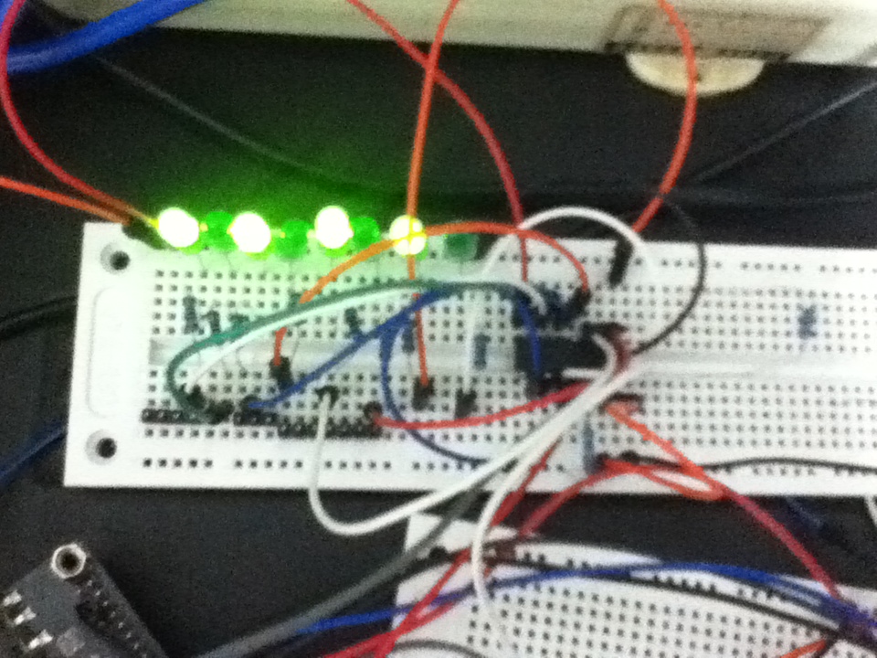
一亮一暗
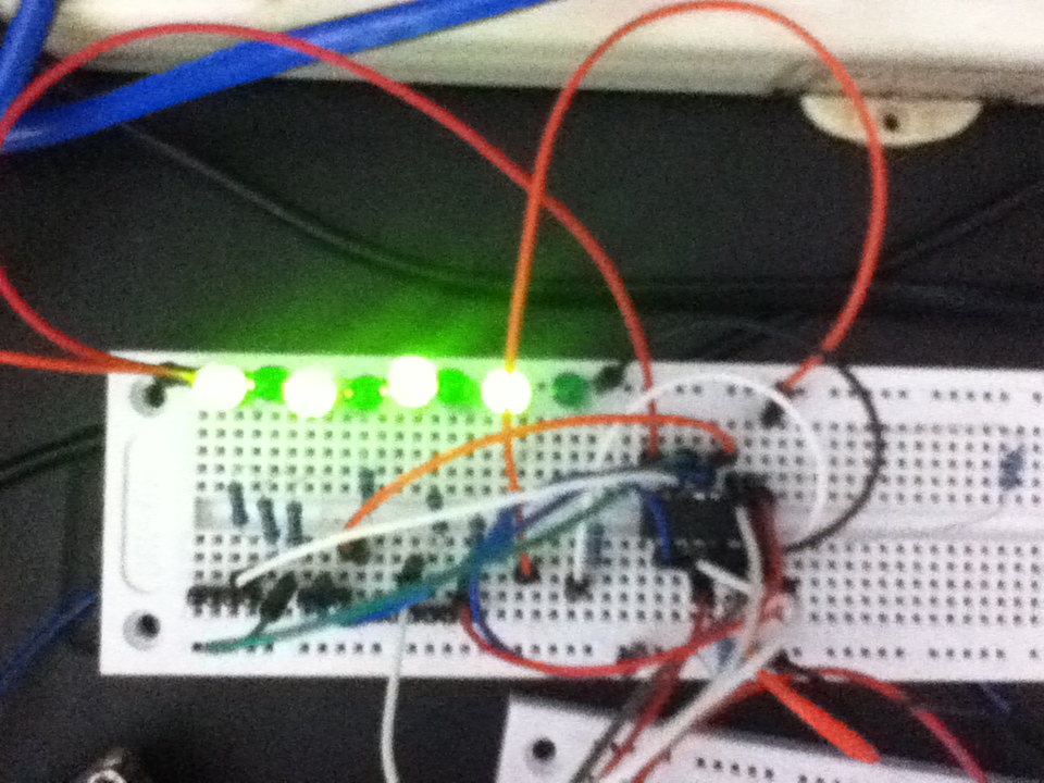
正面照~
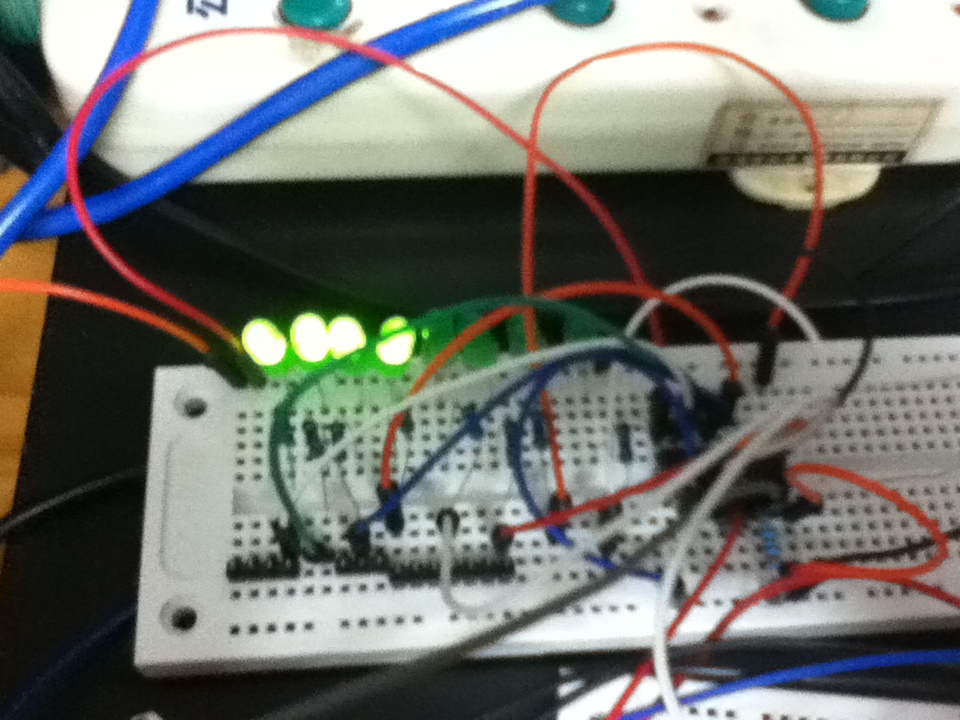
亮4个
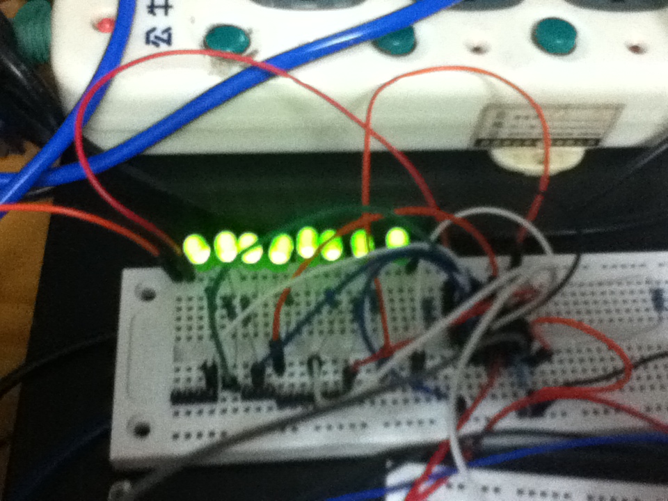
全亮
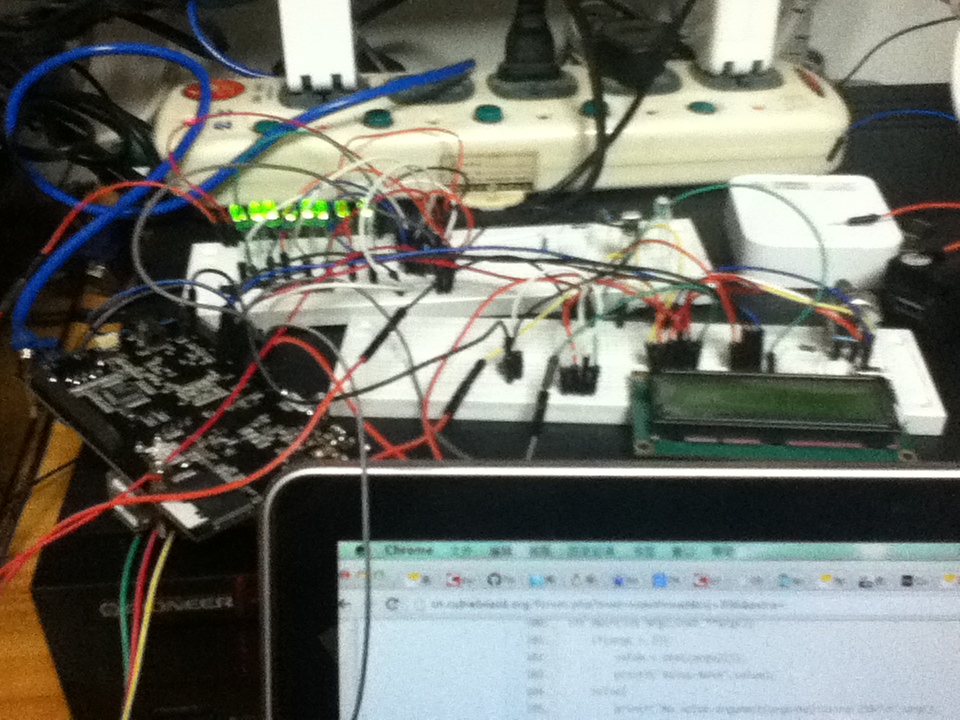
工作图
【END OF PICTURES】
在这里感谢一些人:
1.windland,告诉我怎么在arduino上弄595
2.hipboi,开发出如此好玩的产品——Cubieboard并且弄出了个pySUNXI写寄存器操作GPIO
3.soloforce,把pySUNXI改编了,直接把pySUNXI的C代码弄出来控制
4.忘了叫啥,Arduino开发者,要不是这个人,我代码都不知道哪来的
5.全体支持Cb的人
电路其实没啥好说的,按照arduino的程序图接,latchPin接到PD2,clockPin接到PD3,dataPin接到PD4(因为有一些口我接了1602,所以调了一下)
主程序源代码如下,具体的程序压缩包+电路图晚点给(还是这句):- #include <stdio.h>
- #include <stdlib.h>
- #include "gpio_lib.c"
- #include <string.h>
- //#define LOW 0
- //#define HIGH 1
- //Pin connected to ST_CP of 74HC595
- int latchPin = 2;
- //Pin connected to SH_CP of 74HC595
- int clockPin = 3;
- ////Pin connected to DS of 74HC595
- int dataPin = 4;
- int value = 255;
- typedef unsigned char byte;
- void pinMode(int pin,int io){
- printf("set %d mode to %d \n",pin,io);
- if(SETUP_OK!=sunxi_gpio_set_cfgpin(SUNXI_GPD(pin),io)){
- printf("Failed to config GPIO pin\n");
- //return -1;
- }
- }
- void digitalWrite(int pin,int hl){
- printf("set %d value to %d \n",pin,hl);
- if(sunxi_gpio_output(SUNXI_GPD(pin),hl)){
- printf("Failed to set GPIO pin value\n");
- //return -1;
- }
- }
-
- void *convert(int n)
- {
- int len=sizeof(int)*8; //int型所占数据宽度
- int i;
- for(i=0;i<len;i++)
- {
- putchar('0'+((unsigned)(n<<i)>>(len-1))); //先左移,再逻辑右移,就把二进制从高位到低位输出了
- // printf("%d",((unsigned)(n<<i)>>(len-1))); //也可以这样输出
- }
- printf("\n");
- //printf("\n%d\n",n);
- }
- void shiftOut(int myDataPin, int myClockPin, byte myDataOut) {
- // This shifts 8 bits out MSB first,
- //on the rising edge of the clock,
- //clock idles low
- //internal function setup
- int i=0;
- int pinState;
- pinMode(myClockPin, OUTPUT);
- pinMode(myDataPin, OUTPUT);
- //clear everything out just in case to
- //prepare shift register for bit shifting
- digitalWrite(myDataPin, 0);
- digitalWrite(myClockPin, 0);
- //for each bit in the byte myDataOut
- //NOTICE THAT WE ARE COUNTING DOWN in our for loop
- //This means that %00000001 or "1" will go through such
- //that it will be pin Q0 that lights.
- for (i=7; i>=0; i--) {
- digitalWrite(myClockPin, 0);
- //if the value passed to myDataOut and a bitmask result
- // true then... so if we are at i=6 and our value is
- // %11010100 it would the code compares it to %01000000
- // and proceeds to set pinState to 1.
- int ia = 1<<i;
- int ips = myDataOut & ia;
- if (ips) {
- pinState= 1;
- }
- else {
- pinState= 0;
- }
- printf("DATA: %d\n",myDataOut);
- convert(ia);
- convert(myDataOut);
- convert(ips);
- //Sets the pin to HIGH or LOW depending on pinState
- digitalWrite(myDataPin, pinState);
- //register shifts bits on upstroke of clock pin
- digitalWrite(myClockPin, 1);
- //zero the data pin after shift to prevent bleed through
- digitalWrite(myDataPin, 0);
- }
- //stop shifting
- digitalWrite(myClockPin, 0);
- }
- void init_gpio(){
- if(SETUP_OK!=sunxi_gpio_init()){
- printf("Failed to initialize GPIO\n");
- //return -1;
- }
- }
- int main(int argc,char **argv){
- if(argc > 1){
- value = atoi(argv[1]);
- printf("Value:%d\n",value);
- }else{
- printf("No value argument(argc=%d)!Using 255!\n",argc);
- }
- init_gpio();
- pinMode(latchPin, OUTPUT);
- digitalWrite(latchPin, 0);
- shiftOut(dataPin, clockPin, value);
- digitalWrite(latchPin, 1);
- return 0;
- }
执行“./595 数字”,数字是十进制数,转换成2进制就明白了
常用:
255 = 11111111
170 = 10101010
240 = 11110000
0 = 00000000
右边二进制,左边十进制,1就是高电平,0是低电平
提示:这个程序是从低到高位输出,新手可能不知道,意思是:从右到左看,即最右边那个是595的输出口0,右数第二个是输出口1,以此类推,多试几次就知道了,至于我的灯的顺序为什么是正的,那是因为我把灯反着接了,595的输出口0接到灯8,输出口1接到等7,依次类推
|
 |Archiver|手机版|粤ICP备13051116号|cubie.cc---深刻的嵌入式技术讨论社区